Tanmay J.
Industrial Designer
Professional Assignment | Original Design Solution
June - August 2015
Troy-Bilt ® Battery Charger
A new charging solution for innovative lawn-care Power Tools


Design Objective
MTD's revolutionary CORE™ motor for their Troy-Bilt® Prosumer line, demanded a renewed push for their gas-less, battery powered, lawn-care power tools. With a new product line, arose the need for a new battery charging system.
The focus of this project was creating a design solution that is realized through problem solving, user experience as well as aesthetic exploration - all within the confines of available resources and planned timelines.
UPDATE | The battery charger is now at retail. Click on the adjacent link to take a look at the product listed for sale on Troy-Bilt® website.
THE IDEAS.
Ideation | Thumbnail Sketches
Concept Development | Iterative Sketches


STEP 1. Basic, rough sketches. Preliminary Concept Sketches - Used for form exploration and as underlays for future iterations.

STEP 3. Refinement sketches. With parallel development in 3D modeling, the form factor, functionality and size constraints are accounted for, and a primary sketch render is generated for evaluation.

STEP 2. The concept sketches begin to take form with details and preferences based on preliminary sketch concepts.
STEP 4. Back to the drawing board. With update on internal component requirements and to align with the Visual Brand Language, new iterative concept sketches are generated. All details and functional considerations are accommodated.
STEP 5. With parallel 3D CAD development, sketches are further refined to aid the 3D modeling process. Details are added, dimensions are revised, form is refined, while user experience and production is streamlined. These concept sketches are used to communicate with various inter-disciplinary teams and stakeholders.

STEP 6. Technical details and injection molding considerations are communicated through iterative design sketching. DFM (Design for Manufacturability) is explored here to test the validity of the proposed form factor with engineering teams and suppliers.
FINAL STEP. A final presentation render is generated, which accurately represents the intention of the final concept, for the experience, form, functionality, and branding.
THE SOLUTION.
With Concurrent Design Development using sketches, 3D modeling and prototyping, the final solution is executed. The files are prepared and appropriate information is handed off to engineering, suppliers, graphic design teams, as well as marketing. ID team stays involved for iterative changes and trouble-shooting, all the while ensuring that the design intent is preserved right through manufacturing and sales.
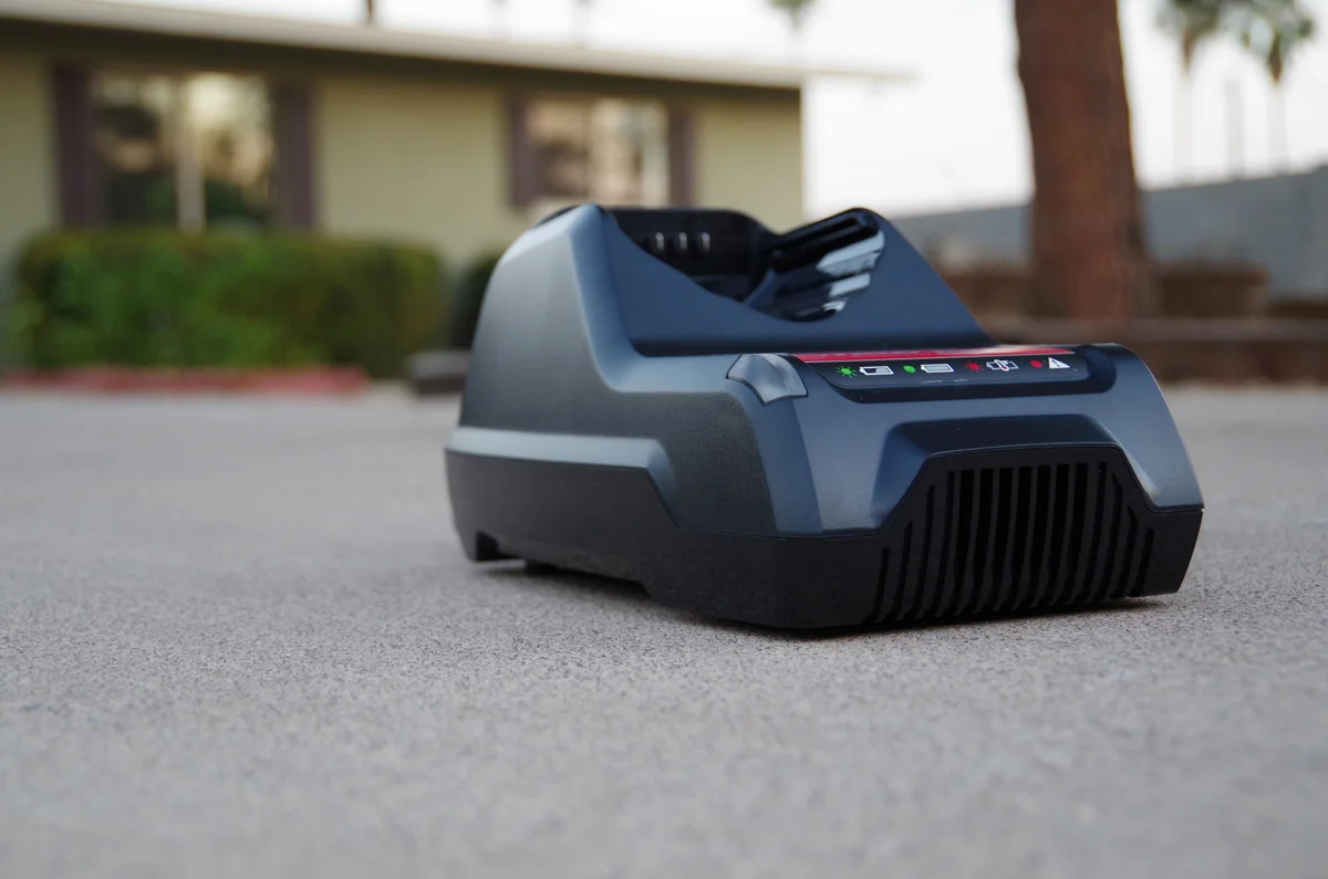
Actual Production Sample


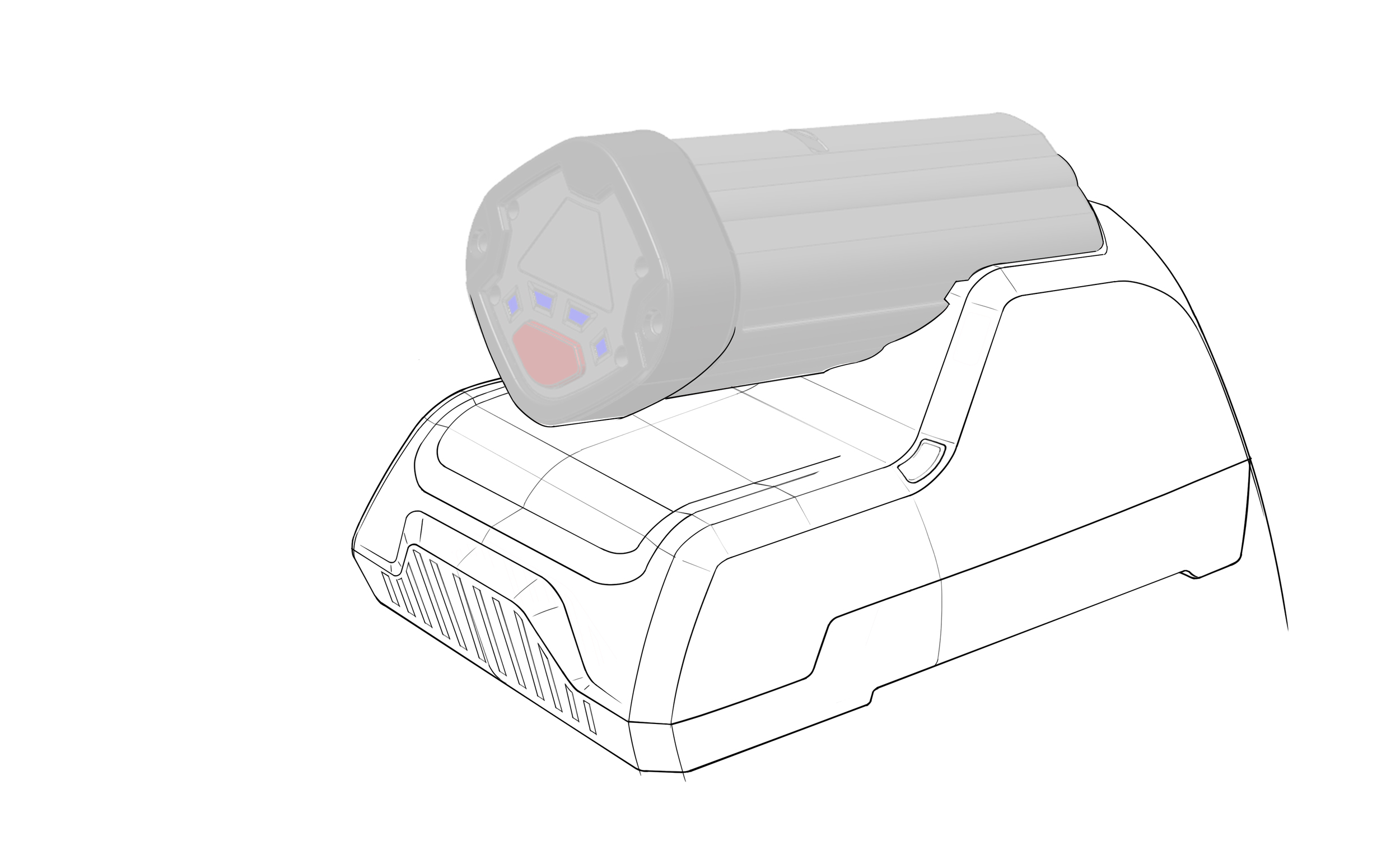
Light Behaviour | Status Indicator
LED User Interaction is proposed based on an extensive competitor research, along with good design practices - all within the capabilities and timelines of the project.


(Please contact me to request a detailed look at the RESEARCH FINDINGS and INSIGHTS presentation)
Here's a mock-up render indicating the mood and context for the Troy-Bilt line of products, with the focus on the battery charger in this particular image. The colour choices here indicate the initial CMF plan for production.
Context Rendering
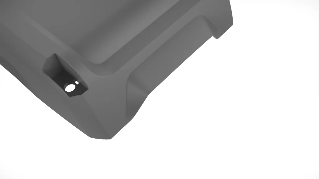
EXTRAS.
Here are some sample renders showing a glimpse of the DFM details for the charger components. This was a collaboration between ID and Engineering (CAD) Departments, where the final technical minutiae was resolved by the experienced CAD staff.